Tuesday 12 March 2019

How to perform Configuration Backup/Restore in Palo Alto Firewall

Palo Alto Configuration Backup


Step1: Navigate to Device > Setup > Operations after login into palo alto firewall.


Step2:  Click on Save named configuration snapshot to save the configuration locally to Palo alto firewall.


Step3: Click on Export Named Configuration Snapshot to take the backup of Palo Alto Configuration file into local PC.


Palo Alto Configuration Restore

Step1: Click on Import Named Configuration Snapshot to Import the saved configuration file into the Palo Alto Firewall.


Step2: Click on Load Named Configuration Snapshot to load the configuration file into Palo alto firewall.


Step3: Click on Commit to save the imported configuration file into Palo Alto Firewall.


MD.Kareemoddin

CCIE # 54759

Friday 8 March 2019

How to convert Mobility Express Image to CAPWAP Image?

--> I recently got the chance to work with some Cisco 1832i APs and Cisco 3504 wireless controller.

--> The problem I faced with Cisco 1832i AP is, they were not able to join to the wireless controller.

--> When I did console to the Cisco 1832i AP and find out the operating system installed in the access point is Mobility Express Image.

--> In order to join this Cisco 1832i AP to the wireless controller, we need to convert Mobility Express Image to Capwap Image.


--> Follow the below steps to convert Mobility Express Image to CAPWAP Image,

Step1: Login into the CLI of the Access Point

Step2: Navigate to Privilege Mode from user mode.

AP>enable

password:

AP#

Note: Password was set during the initial configuration or you can use Cisco

Step3: Execute the following command in the privilege mode.

AP# ap-type capwap

Note: Once you execute the above command then the access point reboots and gets connected with Wireless Controller.

How to manually join Light Weight AP to Cisco WLC?

Step1: Login into the Access point, which you are facing the issue in joining the controller automatically.

Step2: Verify if the access point is associated with any wireless controller by using the following command.

ap#show capwap ip config

Step3: If there is any wireless controller associated to access point and you want to remove that association then execute the following command.

ap# clear capwap private-config

Step4: Execute the following command to join the Access point to Wireless Controller manually,

ap# lwapp ap controller ip address < wireless controller ip address>

or

ap# capwap ap controller ip address < wireless controller ip address>


Note: Once you execute the above command then the Access Point tries to download the operating
system from Wireless Controller. We will not be able to do any changes on access point during this process. Once the software is downloaded from wireless controller then Access Point reboots and joins with the wireless controller.

Friday 8 February 2019

Introduction F5 ASM Attack Signature Sets

--> Attack Signatures are the rules and patterns which identifies the attacks in a request to access the web application.

--> Attack Signatures are the basis for negative security model in ASM.

--> Whenever ASM receives any request for the web application, it checks for attack signatures enabled on the security policy.

--> If the request matches the attack signature then ASM triggers a violation based upon the mode request will be blocked ( Blocking Mode) or will not be blocked ( Transparent Mode).

--> Attack signatures works by buffering and holding different parts an HTTP request for inspection.

--> Attack Signatures in ASM of two types,

i) System Defined Attack Signatures: These are the signatures created by F5 and added to the attack signature pool.

ii) User Defined Attack Signatures: These are the signatures created by the Administrator and added to the attack signature pool.

--> Individual signatures cannot be applied to security policy. An Attack signature is set is assigned to security policy

--> An attack signature set is a group of individual attack signatures.

--> By default, Generic Attack Signature Set is applied to new security policy.

--> ASM Module comes with more than 2000 predefined attack signatures.

--> We can update these signatures using manual method or automatic method.

--> In Automatic Method, BIG IP system downloads the update file by using its own self IP address.

--> In Manual Method, BIG IP Admin needs to download the update file from downloads.f5.com

--> Updating Attack signatures provide updates to existing attack signature sets as well as adds new signature sets to the ASM.


--> Prior to version 13, attack signatures which are updated or new signatures placed into staging state.

--> From Version 13, we can select which attack signatures need to be placed in staging state.

--> In order to update attack signatures automatically, BIG IP ASM needs to have access to following Servers:

1) callhome.f5.com

2) activate.f5.com

--> If you want to know latest security announcements, attack signature updates by subscribing to F5 security Alerts mailing list ( https://interact.f5.com/F5-Preference-Center.html).

Ref: F5.com

Md.Kareemoddin

CCIE # 54759

Tuesday 22 January 2019

What are the different types of vPC?

Single Sided vPC

--> In single-sided vPC, Access devices are connected to Nexus 7K series devices using vPC domain.

--> The access device which is attaching to vPC domain can be of any device such as Layer 2 Switch, Rack Mount Server, Blade Server, firewall, load balancer or any Network Attached Storage ( NAS) device.

--> The only requirement for an Access device in order to connect to vPC is to support Port channel or Link Aggregation feature.


--> The following are the Port-channel protocols supported by Nexus 7K for vPC:

1) LACP

2) Static

--> It is recommended to configure LACP Protocol when forming vPC using access devices.


Double-Sided vPC

--> In Double-sided vPC, Access devices are connected to Nexus 5K series devices using vPC domain and these 5k Series devices are connected to 7K forming one more vPC for the L2/L3 default gateway.

--> vPC domain at the bottom is used for active/active connectivity from endpoint devices to the network access layer.

--> vPC domain at the top is used for active/active FHRP in the L2/L3 boundary aggregation layer.

--> Double-Sided vPC provides higher bandwidth in the network compared to Single-Sided vPC.


Multilayer vPC

--> A dedicated layer of vPC domain (adjacent to aggregation layer which also runs vPC) is used to interconnect the 2 data centers together.

--> Another design is to interconnect directly between vPC aggregation layer, without using any dedicated vPC layer for DCI

--> vPC as DCI technology is intended to interconnect two data centers in maximum.

--> Use vPC to interconnect a maximum of 2 data centers. Use OTV when more than 2 data centers need to be interconnected.


Ref: Cisco.com

Md.Kareemoddin

CCIE # 54759

Sunday 20 January 2019

How to configure Single attached device in vPC

Option 1:

--> Connect the Device to vPC attached access switch.

--> No configuration is required in vPC domain.

--> Provides minimum downtime in case of a peer link failover.

--> The problem with this type of setup is we need to manage additional switch which creates additional administrative overhead.


Option 2:

--> Connect the Device to vPC peers ( Primary or Secondary) by using a Non-vPC VLAN.

--> non-vPC VLAN is a VLAN that is not part of any vPC and not present on vPC peer-link.

--> We need to create a special port-channel between vPC peers to forward this non-vPC VLAN traffic.

--> Access device can be connected to primary peer device or secondary peer device.

--> It does not matter because the dedicated port-channel guarantees a backup path in case vPC peer-link fails down.

--> The problem with this type of setup is we need to manage additional Port-Channel between the vPC Peers.


Option 3:

--> Connect the Device to vPC Primary peer or Secondary peer using vPC VLAN.

-->vPC VLAN is a VLAN that is allowed on vPC Peer-link.

--> No need to create a special port-channel between vPC peers to forward traffic as it uses peer-link for traffic forwarding.

--> But the problem with this type of connectivity is When the Peer-link goes down then the access devices which are connected to Secondary peer loses the connectivity.

--> This type of devices are called as Orphan Devices and Ports that are connected to Nexus 7K peer is called as Orphan Ports.

--> It is recommended to connect the single attached devices to vPC Primary Peer so that in case of peer link failure that does not affect the connectivity.


Ref: Cisco vPC design guide

Md.Kareemoddin

CCIE # 54759


Thursday 17 January 2019

Understanding vPC Components

--> vPC is a virtualization technology that allows two Cisco Nexus 7000 or 5000 Series as a Single Virtual node to downstream devices.

--> The Downstream device can be a switch, server, or any other networking device which supports link aggregation technology.

--> vPC architecture contains the following components:

1) vPC Member

--> This is also called as vPC Peer device.

--> It can be a Nexus 5000 or Nexus 7000 Series Switch.

2) vPC Domain

--> vPC Domain contains two vPC Peer devices.

--> Only 2 peer devices max can be part of same vPC domain.

--> The domain ID must be the same on both peer devices.

--> vPC domain identifiers must be different on both layers because this information is used as part of the LACP protocol.


3) vPC member Port

--> This is one of the port which forms vPC.

--> This Port is connected to both of the Nexus 5000/7000 Upstream switches.
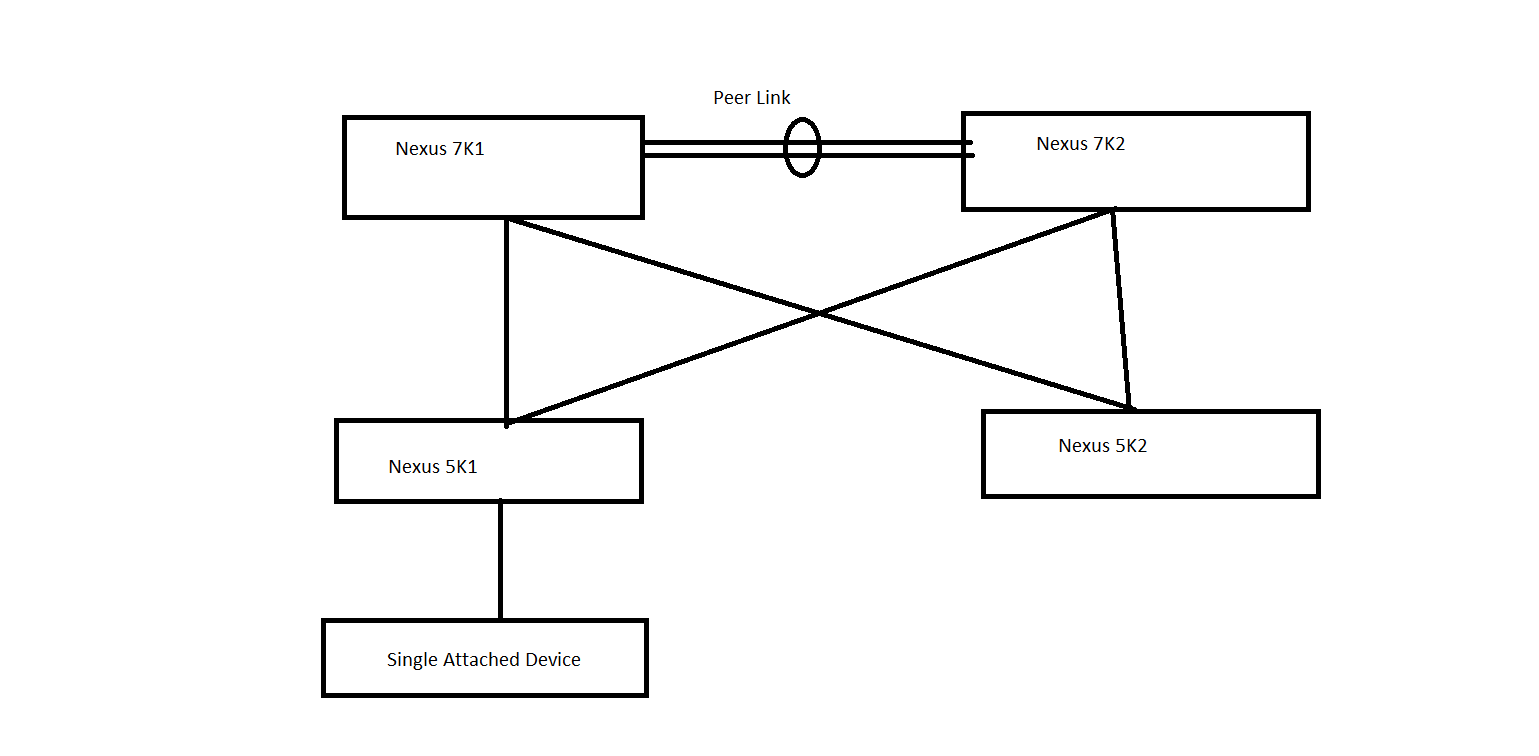
4) Orphan Port

--> A port that belongs to a single attached device.

--> A port on vPC peer device (primary or secondary) that is connected to a single attached device.

--> A port on vPC peer device (primary or secondary) that carries vPC VLAN.

--> If the port carries a non-vPC VLAN, it is no more defined as Orphan Port.

--> When connecting a single-attached access device to vPC domain using vPC VLAN, always connect it to vPC primary peer device.

-->  Reason is when vPC peer-link fails down, any single attached device connected to secondary peer device (and using vPC VLAN) will become completely isolated with the rest of the network.


5) vPC peer-link 

--> This Link used to synchronize the state between vPC peer devices.

--> It must be a 10-Gigabit Ethernet link.

--> vPC peer-link is an L2 trunk carrying vPC VLAN.

--> Cisco Fabric Service protocol is used for synchronizing the state information between vPC Peers.

--> vPC Peer-link can be formed only with the Same family of modules ( F3-F3 and M3-M3).

6) vPC peer-keepalive link 

--> The keepalive link between vPC peer devices; this link is used to monitor the liveness of the peer device.

--> It is recommended to use  1Gbps link for vPC Peer-keepalive link.

--> vPC Peer-Keepalive link must be configured before configuring vPC Peer-link.

--> vPC Peer-Keepalive link uses UDP port number 3200 to check reachability between vPC peers.

--> It is recommended to use separate VLAN interface in different VRF for the peer-keepalive link.

--> vPC Peer-Keepalive just requires reachability ( Both VPC Peers can use different Subnet IP Address for Peer-Keepalive).

--> vPC Peer-Keepalive use management VRF by default for checking the reachability between them.

7) vPC VLAN 

--> VLAN carried over the vPC peer-link and used to communicate via vPC with a third device.


--> vPC VLAN is simply VLAN which is allowed on the peer-link.

8) non-vPC VLAN

--> non-vPC VLAN A VLAN that is not part of any vPC and not present on vPC peer-link.


9) Cisco Fabric Services (CFS)


--> CFS is the protocol used between vPC peers to share and synchronize the state between vPC peer devices.

--> Cisco Fabric Services (CFS) protocol performs the following functions:

? Configuration validation and comparison (consistency check)

? Synchronization of MAC addresses for vPC member ports

? vPC member port status advertisement

? Spanning Tree Protocol management

? Synchronization of HSRP and IGMP snooping

--> Cisco Fabric Services is enabled by default when vPC feature is turned on.

--> There is no specific Cisco Fabric Services configuration to implement.


10) vPC System-Mac and vPC Local System-Mac

--> Once vPC domain is configured both the vPC peers will be assigned with the same MAC address known as vPC System-MAC.

--> vPC system-mac = 00:23:04:ee:be:<vpc domain-id in hexadecimal>

--> It is possible to configure manually vPC system-mac value with the command system-mac inside vPC domain configuration.

--> vPC local system mac is owned by each peer devices so it is unique per device. vPC local system mac is derived from the system or VDC mac address.

--> vPC system-mac is used only with vPC attached access devices while vPC local system-mac is used with single attached devices.

Ref: Cisco.com

Md.Kareemoddin

CCIE # 54759